My type 2a Nixie clocks are a simple extension of my type 1a design to two tubes. The only significant new feature is optional lead zero blanking for appropriate values (hours in 12 hour format, month, and day). There is a new test/demo mode that displays all digits on both tubes (00, 11, 22, ... 99), but this is mainly for my own use in initially configuring the clock, and taking pictures for the animated mockup.
General features of type 2a clocks:
Two-digit display, showing the time and/or date sequentially with a user-settable duration per digit pair and for the gaps between digits. The gap isn't nearly as important as on a one-digit clock, but it can still help readability when pairs of digits are repeated (as at 12:12).
Timekeeping based on the 60 Hz powerline frequency (which has extremely good long-term accuracy), plus a backup capacitor to keep the clock running at reduced accuracy during a power failure. The date and all display options are stored in EEPROM, so that generally only the time will have to be reset even if backup power is exhausted.
Datekeeping is fully Y2K compliant, and is valid through the year 9999.
Three-button user interface - a SET button which steps through the settable values, and UP/DOWN buttons (which may actually be different directions on a momentary toggle or rocker switch) to increment or decrement the selected value. Pressing UP and DOWN simultaneously (if possible on a given clock) increments the value by 20. When not in set mode, UP and DOWN momentarily produce an alternate display - for example, they can be configured to display the date if that isn't part of the normal display.
Currently based on a PIC16F84A processor (will probably switch to the 16F628 once my current stock runs out). 543 out of 1024 words of program EEPROM are used, and about 38 bytes of RAM.
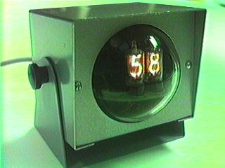
The first clock of this type I built has the following specific features:
Uses a pair of 0.55" digit height Nixies, mounted on a Burroughs plug-in card of unknown original purpose.
Housed in an old Bud analog meter case, with the tubes mostly within a clear plastic dome that exactly fit into the opening for the meter. This allows good visibility of the tubes from almost all directions, without leaving them dangerously exposed as is all too common among Nixie clock designs. Dimensions are roughly a 4" cube, 5 3/8" high including the switches on top. The clock weighs 1 pound 5 ounces.
The UP/DOWN switches are large pushbuttons mounted in the pre-drilled holes where binding posts would normally be mounted on a meter case like this - indeed, they look a lot like a certain style of binding post. The SET switch is a smaller pushbutton mounted between the other two, with the button filed down so that a pen or other pointed object is needed to activate it.
Click here for a copy of the instructions for setting the clock, in Acrobat PDF format.
Click here for some pictures of the circuitry inside the #1 clock.
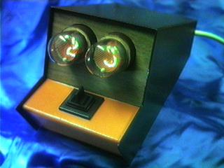
The second type 2a clock is functionally identical to the first, just in a slightly different case style:
0.5" digit height Nixies in this one, although on a plug-in card otherwise identical to #1.
Housed in a LMB Adjusta meter case this time, with a tilt bracket that allows some new mounting possibilities such as the underside of a shelf. Dimensions are roughly 5" wide, 4.5" tall, and 4.5" deep. The clock weighs 1 pound 8 ounces.
UP/DOWN are combined into a momentary paddle switch, so the fast advance setting feature isn't available on this clock. All the controls are on the back, out of sight.
Click here for a copy of the instructions for setting the clock, in Acrobat PDF format.
Click here for some pictures of the circuitry inside the #2 clock.
The third 2a clock: yet another case style...
Russian IN-1 Nixies, with 0.65" digit height, and upside-down "2"s instead of proper "5"s!
Enclosure came from an early 70's Lab-chron electromechanical timer. 4" wide, 8" deep, 4.25" tall at the highest point, 3 lb. 2 oz. weight.
Like #2, the UP/DOWN controls are combined into a single switch, but it's on the front this time.
Click here for a copy of the instructions for setting the clock, in Acrobat PDF format.
Click here for some pictures of the circuitry inside the #3 clock.
 The second type 2a clock is functionally identical to the first, just in a slightly different case style:
 The third 2a clock: yet another case style...