My type 1a Nixie clocks have the following general features:
One-digit display, showing the time and/or date sequentially with a user-settable duration per digit and for the gaps between digits. A brief gap is needed in order to make times with repeated digits (such as 11:12:22) readable, although the gap time can be reduced to zero if the user really wants to.
Timekeeping based on the 60 Hz powerline frequency (which has extremely good long-term accuracy), plus a backup capacitor to keep the clock running at reduced accuracy during a power failure. The date and all display options are stored in EEPROM, so that generally only the time will have to be reset even if backup power is exhausted.
Datekeeping is fully Y2K compliant, and is valid through the year 9999.
Three-button user interface - a SET button which steps through the settable values, and UP/DOWN buttons (which may actually be different directions on a momentary toggle or rocker switch) to increment or decrement the selected value. Pressing UP and DOWN simultaneously (if possible on a given clock) increments the value by 20. When not in set mode, UP and DOWN momentarily produce an alternate display - for example, they can be configured to display the date if that isn't part of the normal display.
Currently based on a PIC16F84A processor (will probably switch to the 16F628 once my current stock runs out). 491 out of 1024 words of program EEPROM are used, and about 42 bytes of RAM.
The first clock of this type I built has the following specific features:
Uses a calculator-style Nixie tube with 0.5" digit height.
Housed in an AC adapter case, designed to be plugged directly into an AC outlet. Dimensions are approximately 2" wide, 2 5/8" high (3 1/4" including the switch handle), and 1 3/4" deep (2 3/8" including the prongs).
The SET button is a magnetic reed switch at the lower front of the case, to prevent accidental changes to the time. The UP/DOWN features are done by pushing a momentary toggle switch on top of the clock to the right or left.
Click here for a copy of the instructions for setting the clock, in Acrobat PDF format.
Click here for some pictures of the circuitry inside the #1 clock.
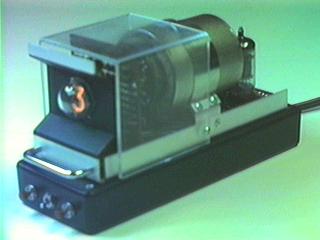
My second clock of this type is about as different as can be, yet uses basically the same design. It is based on a Burroughs Beam-X decimal counter module, although the Beam-X tube is not actually used by the clock.
Click here for the auction description of the #2 clock, including an animated mockup.
Click here for interior pictures and technical details.
 My second clock of this type is about as different as can be, yet uses basically the same design. It is based on a Burroughs Beam-X decimal counter module, although the Beam-X tube is not actually used by the clock.