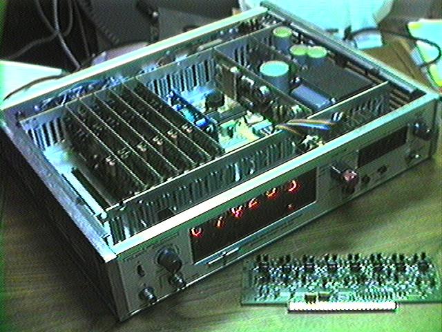
 Here's the clock with the top cover removed. The counter's original construction was 14 individual circuit boards plugged into a motherboard: I have removed six of those boards (leaving only the power supply and Nixie drivers), replacing them with a single board using a modern microcontroller to run the clock. One of the removed boards is shown in front of the clock: it contains 16 transistors and implements a two-digit decimal counter. The buyer will receive a few of the extra boards, as examples of the clock's original technology without having to remove the cover.
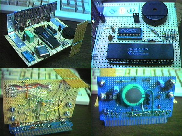 Here's the one board I added. The right-angle design was the best I could think of, using the parts on hand, that would allow me to easily remove and replace the processor for software updates without having to pull the entire board each time. I would have done this quite differently if the counter still had the extender board that originally came with it! The piece of perfboard with no components on it fits into another edge connector on the motherboard, to help stabilize the board (since it isn't wide enough to reach the guides at the edges of the card cage).
The processor is a Microchip PIC16C64A, running at 4 MHz. The clock software uses 933 out of 2048 words of program EPROM, and 47 out of 128 bytes of RAM.
The interface with the counter's existing circuitry was complicated by the fact that it uses 10 volt logic, instead of the 5 or less volts used by almost all modern digital electronics. The smaller chip is a 4504 CMOS level shifter, which is sufficient for driving the count inputs on the Nixie boards. However, the reset input, shared by all boards, requires about 26 mA of current at 10V to operate (it was 65 mA before I removed the boards that are no longer needed), which is far beyond the 4504's drive capability. For this one signal, I use a UDN2951Z half-bridge driver to do the level shifting - this is massive overkill (it's rated at a few amps), but has the distinct advantage that I actually had one on hand, and didn't need it for anything else.
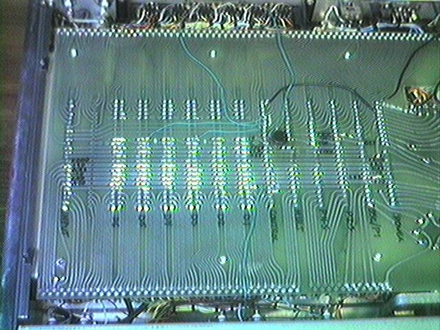 Here's the bottom of the clock with the cover removed, showing the motherboard. All I had to do here was run a few wires to bring signals to the slot where my processor board is installed. Also, the power switch has been rerouted so that it only turns off the high voltage to the Nixies, instead of the entire power supply (which isn't generally a desirable feature in a clock!).
There aren't enough pins on the edge connectors to get all the needed signals to the processor board that way, so there's also a direct connection from the front panel switches via a ribbon cable and 16-pin DIP header.